Matching and Pelgrom’s law
A chip can’t hold a resistor to better than ±12.5 %, and yet people build 12-bit converters on chips like that. They manage it by never asking the chip for a particular value, only for a ratio between two values.
This is the most important idea in analog IC design. The arithmetic behind it fits on one line, but it’s rarely taught in a first circuits course, which is a shame, because it explains why most analog schematics look the way they do.
Ratios across corners
The corners deck from Process corners also prints a second set of numbers for each corner: two resistors drawn in a 1:4 ratio, the ratio of their values, and the output of a divider made from them:
--- ll : absolute (moves) ---
r_a = 3.106637e+03
r_b = 1.143366e+04
--- ll : ratio and divider (do not move) ---
ratio = 3.680396e+00
divider = 3.845828e-01
--- tt : absolute (moves) ---
r_a = 3.550443e+03
r_b = 1.306704e+04
--- tt : ratio and divider (do not move) ---
ratio = 3.680396e+00
divider = 3.845828e-01--- hh : absolute (moves) ---
r_a = 3.994248e+03
r_b = 1.470042e+04
--- hh : ratio and divider (do not move) ---
ratio = 3.680396e+00
divider = 3.845828e-01Here are the same numbers in one table:
ll |
tt |
hh |
spread | |
|---|---|---|---|---|
| \(R_A\) | 3106.637 Ω | 3550.443 Ω | 3994.248 Ω | ±12.5 % |
| \(R_B\) | 11 433.66 Ω | 13 067.04 Ω | 14 700.42 Ω | ±12.5 % |
| \(R_B / R_A\) | 3.680396 | 3.680396 | 3.680396 | 0 |
| divider out | 0.3845828 V | 0.3845828 V | 0.3845828 V | 0 |
The ratio and the divider output agree to every printed digit. Between the ll and hh runs each resistor swung by a quarter of its value, yet the divider built from the two of them didn’t move at all. You’ll run this deck yourself in Lab 04, Part 1.
Why the ratio holds
A corner doesn’t add a fixed offset to a resistor’s value; it applies a multiplier, and every device made of that material gets the same factor \(k\):
\[\frac{R_B}{R_A} = \frac{k\,R_{\square}\,L_B/W}{k\,R_{\square}\,L_A/W} = \frac{L_B}{L_A}\]
Both \(k\) and \(R_\square\) cancel, and so does any error in the width, as long as you draw both resistors the same width. What’s left is the ratio of the two lengths you drew, and lengths on a mask are held to within nanometres.
The same arithmetic explains why the printed ratio is 3.680396 rather than the 4.0 you drew. The bodies are in the ratio \(L_B/L_A = 40/10 = 4\), but each device also carries 378.2448 Ω of end resistance (Ohms per square):
\[\frac{R_B}{R_A} = \frac{378.2448 + 317.2198\times 40}{378.2448 + 317.2198\times 10} = \frac{13067.04}{3550.443} = 3.680397\]
ngspice printed 3.680396, so the ends account for the whole difference from 4. The end resistance is a systematic error in the ratio, and changing the corner doesn’t remove it. That’s why real layouts build a 4:1 ratio from four identical unit resistors in series next to a single unit, rather than from one long strip beside one short one. The four units in series have four sets of ends and the single unit has one, so the ends are in the same 4:1 proportion as the bodies, and the ratio comes out 4.000000 at every corner.
That’s the first rule of matched layout, and you can derive it from a printed number:
If you need a ratio, build both sides from repeated copies of the same unit device, never from one big device and one small one.
Mismatch between identical devices
A corner is global: it moves every device made of the same material by the same factor, which is why a ratio cancels it completely. Mismatch is local. Two devices drawn identically still come out slightly different from each other, and a ratio can’t cancel that difference at all, so mismatch sets the floor on how well any ratio can be held.
labs/passives-decks/spice/mismatch.spice runs two hundred Monte Carlo samples with mc_mm_switch=1, which switches on the mismatch terms in the model card (they are multiplied by MC_MM_SWITCH, as you’ll see under Pelgrom’s law below), and uses setseed 12345 so that the numbers are reproducible. (Lab 04 runs a similar experiment starting from setseed 1 and gets 2.5852 % for the 1 µm² device. That’s a different draw from the same distribution rather than a different answer.) The deck has four devices, all of the same material from the same foundry: A and B are drawn 1 µm × 1 µm, and C and D are drawn 10 µm × 10 µm, which is one hundred times the area.
== 5/5  mismatch: 200 wafers, four resistors ==================
   800 measurements recorded

  Monte Carlo: 200 runs, seed 12345
  ok       sigma/mean A (1x1)       2.7930 %   (reference  2.7930 %)
  ok       sigma/mean B (1x1)       2.8775 %   (reference  2.8775 %)
  ok       sigma/mean C (10x10)     0.3045 %   (reference  0.3045 %)
  ok       sigma/mean D (10x10)     0.3479 %   (reference  0.3479 %)
  ok       sigma/mean A/B ratio     3.7695 %   (reference  3.7695 %)
  ok       sigma/mean C/D ratio     0.4496 %   (reference  0.4496 %)
           100x the area bought 8.38x better matching   (Pelgrom's square root of 100 would be 10x)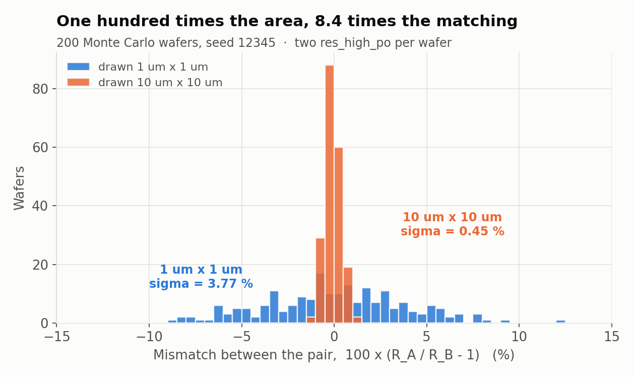
The plot shows two hundred wafers, each with two resistors drawn from the same rectangle. The blue histogram is the 1 µm × 1 µm pair, which routinely comes out 5 % apart and sometimes 12 %. The orange histogram is the 10 µm × 10 µm pair, and almost all of those are within one percent of each other.
Pelgrom’s law
The rule behind that plot is Pelgrom’s law: the mismatch between two identically drawn devices scales as one over the square root of their area.
\[\frac{\sigma_{\Delta R}}{R} = \frac{A_R}{\sqrt{W L}}\]
\(A_R\) is a constant for each process, and SkyWater prints it on the model card, in sky130_fd_pr__res_high_po.model.spice:
+ body_pelgrom = 0.03552
+ head_pelgrom = 0.0761
+ num_con_row = {max(floor(0.5+(w-0.33)/0.36),1)}
+ rbody_match = {body_pelgrom/sqrt(w*l*mult)*MC_MM_SWITCH*AGAUSS(0,1.0,1)}
+ rend_match  = {head_pelgrom/sqrt((w+0.525)*num_con_row*mult)*MC_MM_SWITCH*AGAUSS(0,1.0,1)}
So the body of the resistor matches as \(0.03552/\sqrt{WL}\). The contact heads follow a different law, \(0.0761/\sqrt{(W+0.525)\,n_{\text{contacts}}}\), because a contact head is a row of cuts rather than an area.
Worked example: predicting the Monte Carlo
You can predict what the Monte Carlo will report before you look at it. The head and body resistances of both devices come from running make resistor in labs/passives-decks:
head_l1 = 2.998915e+02    body_l1 = 3.955731e+02    r_l1 = 6.954646e+02
head_10x10 = 3.410354e+01 body_10x10 = 3.247625e+02 r_10x10 = 3.588661e+02
The 1 µm × 1 µm device. \(n_{\text{contacts}} = \lfloor 0.5 + (1-0.33)/0.36 \rfloor = 2\).
\[\sigma_{\text{head}} = \frac{0.0761}{\sqrt{1.525 \times 2}} = 4.357\ \% \qquad \sigma_{\text{body}} = \frac{0.03552}{\sqrt{1}} = 3.552\ \%\]
\[\sigma_R = \sqrt{(299.8915 \times 0.04357)^2 + (395.5731 \times 0.03552)^2} = \sqrt{13.067^2 + 14.051^2} = 19.188\ \Omega\]
\[\frac{\sigma_R}{R} = \frac{19.188}{695.4646} = \boxed{2.759\ \%}\]
Monte Carlo gives 2.7930 % for A and 2.8775 % for B. Two hundred samples pin σ down only to within about \(1/\sqrt{2N} = 5\ \%\) of its own value, so the predicted 2.759 and the measured 2.79 are the same number as far as this experiment can tell.
The 10 µm × 10 µm device. \(n_{\text{contacts}} = \lfloor 0.5 + 9.67/0.36 \rfloor = 27\).
\[\sigma_{\text{head}} = \frac{0.0761}{\sqrt{10.525 \times 27}} = 0.4514\ \% \qquad \sigma_{\text{body}} = \frac{0.03552}{\sqrt{100}} = 0.3552\ \%\]
\[\sigma_R = \sqrt{(34.10354 \times 0.004514)^2 + (324.7625 \times 0.003552)^2} = 1.1638\ \Omega\]
\[\frac{\sigma_R}{R} = \frac{1.1638}{358.8661} = \boxed{0.3243\ \%}\]
Monte Carlo gives 0.3045 % for C and 0.3479 % for D.
The predicted improvement is \(2.759 / 0.3243 = 8.51\times\), and the measured one is 8.38×.
Neither of those is the 10× that Pelgrom’s \(\sqrt{100} = 10\) suggests, because that figure assumes the whole device is body. In the small resistor 43 % of the resistance is contact head, and the heads match as \(\sqrt{(W+0.525)\,n}\), which improved by only 9.7× between the two devices while the body’s \(\sqrt{WL}\) improved by 10×. That’s where the shortfall from 10 to 8.4 comes from. If you had predicted 10×, you would have been wrong, but in a way the model can explain.
Four rules of analog layout
Everything above comes down to four practical rules:
- Build ratios from identical unit devices. A 4:1 ratio is four units against one unit, never a long device against a short one. That removes the end-resistance error, and it also means both sides see the same etch.
- Buy matching with area. For 0.1 % matching, \(\sigma = A_R/\sqrt{WL}\) gives \(WL \approx (0.03552/0.001)^2 = 1262\) µm² per device. Matching isn’t free, and you pay for it in square micrometres.
- Surround the array with dummies. The outermost real unit has a neighbour on one side and empty space on the other, and etch and stress respond to that difference. An extra unit connected to nothing makes every real unit’s surroundings identical.
- Interdigitate, or use a common centroid. The wafer has gradients across it, in temperature, oxide thickness and stress, so two devices placed side by side sit at different points on the gradient. Splitting each device into halves and laying them out
A B B Aputs both devices’ centres at the same point, so a linear gradient cancels exactly.
Rules 3 and 4 are things you draw rather than things you calculate, so they’re taught in AD104, but the reasons for them are all on this page.
How analog circuits use matching
Now go back to the converter at the top of the page. A 12-bit ADC needs an accuracy of 1 part in 4096 from a process that can’t hold a resistor to better than 1 part in 8, and it gets there because none of its accuracy depends on an absolute value:
- a capacitor DAC is a binary-weighted array of identical unit capacitors, so its linearity is a ratio, and the unit is made large enough that Pelgrom’s law gives the required \(\sigma\);
- a current mirror copies a current by making two transistors identical, without needing to know what the current is;
- a bandgap reference produces a voltage from a resistor ratio times \(kT/q\), which depends only on physical constants and the temperature, so the absolute sheet resistance drops out;
- a differential pair, the basic analog building block, only needs its two halves to be the same as each other, whatever their actual values turn out to be.
All four rely on the same idea. Silicon is very good at making two things the same and poor at making one thing a particular value, so analog circuits ask it for copies rather than numbers.
Next on the Course path: Lab 04: Two resistors that disagree. It runs its own Monte Carlo, checks Pelgrom’s law across four device sizes, and ends with a divider specification that a naive two-resistor layout cannot meet. After that comes From schematic to cross-section, which turns the chip on its side and takes your measured 317.2198 Ω/□ back to a material property.
Stuck on anything here? Ask in the team Discord.