SimProc in one page
This page answers: what is this processor, exactly? I need to know what it should do before I can say it does not.
rtl/simproc_system.sv is 1,178 lines, and you don’t need to read it. The machine is small enough to hold in your head, and everything DD104 asks you to do is a question about the machine rather than the file, so this page describes the whole machine instead.
The architectural state
    r0  r1  r2  r3        four 8-bit registers                 32 bits
    PC                    one 8-bit program counter             8 bits
    N   Z                 two flags                             2 bits
    mem[0 .. 63]          sixty-four bytes of RAM             512 bits
                                                              ────────
                                                              554 bits
Those 554 bits are the processor’s entire architectural state, so if two SimProcs agree on them after every instruction, no program can tell them apart. That is the claim the golden model is built to check, and Lab 05 shows you that the claim is not enough.
If you have met RISC-V or MIPS, you know that register zero reads as zero and ignores writes.
r0here is an ordinary register. It holds whatever you last put in it, andORI, the only instruction that can introduce a constant, writes onlyr0. Assuming otherwise will cost you an evening; Lab 03 has you check it in two lines of test.
Three things the machine does not have shape every program you write:
- No carry flag and no overflow flag. Eight-bit arithmetic wraps around without telling you, so
200 + 60gives4. - No compare instruction. You compare with
SUB, which writes the difference intorA, so comparing two values destroys one of them. - No
NOT, noHALT, no stack, no call and no interrupt. You invert a register withNAND rX, rX, and a finished program parks itself inJMP -1.
One byte per instruction
Every instruction is one byte, and three field layouts share the encoding space:
    register form     A A B B o o o o      rA = instr[7:6], rB = instr[5:4]
    branch form       d d d d o o o o      d = 4-bit SIGNED displacement
    3-LSB forms       A A D S S 0 1 1      SHIFT: D = direction, SS = amount
                      i i i i i 1 1 1      ORI:   5-bit immediate
In the register form, rA is both a source and the destination: ADD(1, 2) means r1 = r1 + r2, and there are no three-operand instructions.
SimProc has eleven instructions. The full encoding table, with what each does and what it costs, is The SimProc instruction set; keep it open in another tab. The short version:
| Arithmetic and logic | ADD SUB NAND SHL SHR: all write rA, all set N and Z |
| The constant | ORI imm5: r0 <- r0 \| imm, sets flags |
| Memory | LOAD rA, rB reads mem[rB]; STORE rA, rB writes mem[rB] |
| Control | JMP always; BZ BNZ BPZ on the flags. None of them touch the flags |
| Nothing | 0xC 0xD 0xE are unimplemented and behave like a slow no-op |
The FSM and its timing
The core is a six-state machine: IDLE, then CYCLE_1 to CYCLE_5. It is not pipelined, has no cache and speculates nothing, so a program’s cycle count is the sum of its instructions’ cycle counts and you can add it up by hand before you run it.
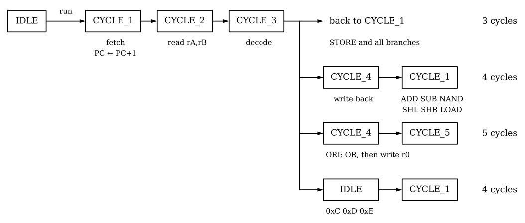
CYCLE_3.Two details of that diagram matter more than they look.
CYCLE_2 reads the register file for every instruction, using instr[7:6] and instr[5:4] as the two register numbers, before anything has decided what the instruction is. On a branch those bits are half of the displacement, but the read happens anyway and its result is thrown away. So a bug in the register-select path can show up on instructions that don’t obviously use registers.
An unimplemented opcode leaves through IDLE. It matches no clause in CYCLE_3, so the FSM takes its default exit, spends one cycle in IDLE, and is sent back to CYCLE_1 by run, which is still asserted. We measured it on a program of four filler bytes (0x0C):
| Clock cycles | 16: four each, not three |
done pulses |
0 |
Cycles with halt high |
4: one per instruction |
So the byte the harness fills unwritten memory with is also the one byte that makes halt blink in the middle of a running program. If you write the assertion “halt must stay low while run is asserted”, as Lab 05 asks you to, it will fire on any program that runs off its own end into filler. When that happens, your test is working correctly and the machine is behaving as designed, and it’s better to learn that distinction here than at midnight.
Cycle counts
| Instruction | Cycles |
|---|---|
ORI |
5 |
ADD SUB NAND SHL SHR LOAD |
4 |
STORE JMP BZ BNZ BPZ |
3 |
0xC 0xD 0xE (unimplemented) |
4, no done, one cycle of halt |
The golden model can run a program on its own, with no simulator underneath it, and its demo program prints this:
16 instructions in memory, 28 executed, 109 clock cycles
registers: r0=32 r1=15 r2=1 r3=32
mem[0x20] = 15   (all 28 instructions executed)
You’ll run it in Lab 02, Part 4. That 109 is exact, and you can derive it rather than take it on trust. Seven setup instructions cost 4+5+4+4+4+5+4 = 30; a three-instruction loop body costs 4+4+3 = 11 and runs five times, for 55; the finish costs 4+5+4+4+4+3 = 24. \(30 + 55 + 24 = 109\). The simulated hardware agrees to the cycle, and test_example.t05_a_loop_and_its_cycle_count asserts exactly this. If your hardware ever reports 114, the five extra cycles over five iterations point to one extra cycle per iteration, which is a much better starting point for debugging than “it is slow”.
The memory
dp_ram is 64 bytes, dual-ported, with combinational reads and no reset.
You’ll rely on the missing reset constantly. Resetting the core clears the registers, the PC and the flags, but leaves your program and its results in memory where they were, and that is what lets a test load a program, reset, and run from a known state.
The size is a trap, because the address bus is 8 bits wide but the array has only 64 entries:
- Reads above 63 return
X. A UARTREADof address0x45puts eight undefined bits on the chip’s TX pin, and in cocotb 2.x, callingint()on that value raises an exception instead of guessing. That is the right behaviour, but the first time you see it, it will look like a harness bug. - Writes above 63 are dropped without any warning, and they don’t wrap around into low memory. When we wrote
0x99to0x45,mem[0x05]was left untouched. - Verilator’s linter reports the mismatch just from reading the file (
Bit extraction of array[63:0] requires 6 bit index, not 8 bits, four times), while Icarus shows it only at run time, asXon a pin. Both are right, but only Verilator tells you before you run anything. See Two simulators.
The harness refuses out-of-range addresses for you, with a message explaining all of the above, so you will normally meet this through a program whose pointer register went somewhere you did not intend.
The chip from outside
SimProc is wrapped in a TinyTapeout pin frame. Seen from outside the package, its whole interface is one serial input pin, one serial output pin, two status pins and a baud divider.
| Pin | Direction | What it is |
|---|---|---|
ui_in[0] |
In | uart_rx: everything goes in here |
uo_out[0] |
Out | uart_tx: everything comes out here |
uo_out[1] |
Out | halt: high while the core sits in IDLE |
uo_out[2] |
Out | done: one-cycle pulse as an instruction retires |
uo_out[7:3] |
Out | Tied to zero |
uio_in[7:0] |
In | The baud divider: clk_per_bit = uio_in × 4 |
uio_out, uio_oe |
Out | Tied to zero; every bidirectional pin is an input |
rst_n |
In | Reset, active low |
ena |
In | Always 1 when powered; ignore it |
The chip’s only test checks uo_out. uo_out == 3 is 0b0000_0011: uart_tx = 1 (an idle serial line sits high), halt = 1 (the core is in IDLE) and done = 0. So checking for that value only asserts that the processor is not running, and Lab 02 is where you watch all thirteen broken cores pass it.
The debug protocol
The only way in from outside is a 3-byte UART command, always three bytes (cmd addr data) even when addr and data are ignored. The serial format is 8N1, with no parity.
| Byte | Command | What it does |
|---|---|---|
0xA3 |
READ |
Replies with mem[addr] |
0x5C |
WRITE |
mem[addr] = data |
0xF0 |
PING |
Replies 0xAA |
0x3F |
RUN |
Start free-running |
0xC7 |
HALT |
Stop |
0x6D |
STEP |
Execute exactly one instruction |
0x99 |
SET_PC |
PC = addr, only while the core is in IDLE |
0xB2 |
GET_PC |
Replies with the PC |
Serial is slow, and we measured how slow. All of these numbers are at the default clk_per_bit = 32:
| Clock cycles | |
|---|---|
| One 3-byte command | 1,104 |
A command with a reply (PING) |
1,353 |
| Loading a 64-byte program over the wire | 70,656 |
| The same program through the harness’s memory backdoor | 2 |
The head start RUN gets: the core is executing this long before the command finishes going out |
57 |
Those numbers are why the harness has a backdoor into the RAM array, and why everything in simproc.py that counts something starts its monitor before sending RUN. They are also why you cannot stop this processor after exactly N instructions: HALT takes 1,104 cycles to arrive and the core runs the whole time. Programs park themselves in a JMP -1 instead, the way real bare-metal test code does.
Where the pieces live
If you do open the file, this is its shape, and these are the paths the harness reaches through:
tb
└── tt_um_ieeeuoftasic_simproc          the pin frame
    └── U1                              simproc_system      lines 1–326
        ├── RAM1.mem[0..63]             64 bytes            lines 827–859
        ├── UART1                       8N1, no parity      lines 863–1178
        └── CPU1                        the core            lines 330–739
            ├── curr_state              IDLE / CYCLE_1..CYCLE_5
            ├── n_flag_out, z_flag_out
            ├── RF1.rf[0..3]            the registers       lines 741–771
            ├── PC1.pc_out                                  lines 773–788
            └── ALU1                    6 ops, N and Z      lines 790–823
Three of those modules are 16, 31 and 34 lines, which is why Lab 03 can test them completely, including all 393,216 ALU vectors, before you reason about the processor as a whole.
simproc.py wraps every one of these paths, so you shouldn’t need to type them yourself.
Five facts that will cost you
Everything above is background. These five facts are the ones most likely to turn into a wrong answer at 1 a.m.:
ORIonly sets bits. RunSUB rX, rXfirst, or you get the OR of everything that register has ever held. This is the most common way to write a SimProc program that is wrong and looks right.ORIalways writesr0, whatever else the program is doing. It has no register field; all five spare bits are the immediate.- Branch displacements are measured from the next instruction, because the PC has already been incremented when the branch computes its target.
JMP(0)falls through andJMP(-1)loops on itself. The range is-8to+7. - Only
ADD,SUB,NAND,SHIFTandORIset flags.LOAD,STOREand every branch leaveNandZexactly as they were, which lets you compare once and branch on the result twice. Relying on that is also an assumption, though, and assumptions get tested. - Shift amounts are two bits: 0, 1, 2 or 3. You cannot shift by 4 in one instruction, and the assembler refuses rather than silently truncating.
Each of those is a place where a wrong implementation and a right one agree on the inputs you would naturally pick, and that is the subject of Where bugs hide.
Check yourself
- Add up the cycles for
SUB r0, r0 ; ORI 5 ; ADD r1, r0 ; STORE r1, r2. - A branch at address 10 has displacement
-3. Where does it go if taken? - Your test reads address 70 through the UART and gets an exception from
int(). Is the harness broken?