Reading DRC errors
Ninety per cent of layout is messing stuff up. — the team lead, and the reason this course is shaped the way it is
A design rule check (DRC) reports each problem in your layout as one sentence, and each sentence says something specific about what the foundry’s equipment can and can’t make. Every rule exists for a physical reason and every violation names the rule it broke, so the rule name tells you what to fix.
The skill this course teaches is a loop: read the rule name, understand the constraint, change one thing, and run the check again. In Lab 02 one pass of that loop takes about four seconds, and you’ll spend a lot of your layout time going round it.
What a violation looks like
Magic runs the check continuously as you draw. It covers each violation with white hatching and keeps a count in the toolbar, and to find out what a particular violation is, you put the box over it and ask:
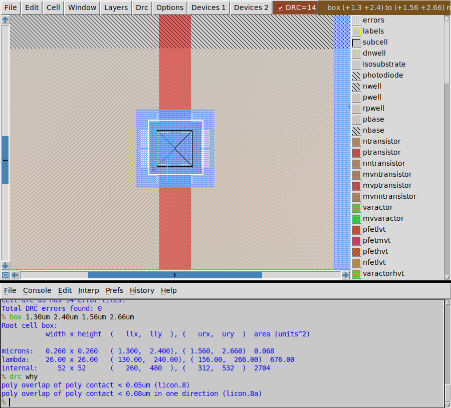
The toolbar says DRC=14, and the white hatching sits around the poly contact. With the box over the hatching, drc why names the rule twice: once as the plain enclosure rule and once as the directional version of it.
% drc why
poly overlap of poly contact < 0.05um (licon.8)
poly overlap of poly contact < 0.08um in one direction (licon.8a)
That’s cell drc_03 from Lab 02. Its poly landing pad has been shrunk to 0.25 × 0.25 µm around a 0.17 µm cut, which leaves 0.04 µm of poly on each side, and the rule asks for 0.05.
The four DRC commands
drc check          ;# re-run the checker over the whole cell
drc catchup        ;# wait for it to finish (batch scripts need this)
drc count total    ;# how many violations
drc why            ;# name the rules broken under the current box
You’ll use drc why the most, because drc count total only tells you how many violations there are, while drc why tells you what they are. When you do want the count, use drc count total rather than plain drc count. The last line of plain drc count is a hierarchical total, and on a cell with no subcells it reads 0.
“In one direction”
You’ll see this phrasing often:
Local interconnect overlap of poly contact < 0.08um in one direction (li.5)
Metal1 overlap of local interconnect contact < 0.06um in one direction (met1.5)
N-diffusion overlap of N-diffusion contact < 0.06um in one direction (licon.5c)
It’s easy to misread this as “0.08 µm somewhere”. What the phrase actually means is: pick an axis, x or y, and on that axis the surrounding layer must extend past the contact by at least that much on both sides.
So a contact centred in a shape that’s generous vertically but tight horizontally passes, because the y axis satisfies the rule on its own. A contact tucked into a corner fails, because neither axis has clearance on both sides.
That’s why the li (local interconnect) strips in Lab 03’s reference inverter are 0.37 µm wide around a 0.17 µm contact. The extra width gives 0.10 µm of overhang on the left and on the right, so the x axis satisfies the rule by itself.
It’s also why the fix for one of these violations is rarely to make everything bigger. Usually you only need to make the shape bigger on one axis, and that often costs no area at all.
The four kinds of rule
Almost every SKY130 rule you’ll meet is one of four kinds:
| Kind | Reads like | Physically |
|---|---|---|
| width | Local interconnect width < 0.17um (li.1) |
the printer can’t resolve a line thinner than this |
| spacing | Metal1 spacing < 0.14um (met1.2) |
two features closer than this merge, or short together |
| enclosure / overlap | N-well overlap of P-Diffusion < 0.18um (diff/tap.8) |
the two masks don’t align perfectly, so you leave a margin |
| area | Local interconnect minimum area < 0.0561um^2 (li.6) |
a shape smaller than this lifts off or doesn’t fill |
Once you can sort a message into one of those four kinds, you know which kind of edit fixes it: make the shape wider, move it away, make the shape around it bigger, or make it bigger overall.
Iterating to a clean layout
The reference inverter in Lab 03 wasn’t drawn correctly the first time. Its first version had 62 violations across seven distinct rules: contacts too close to the edges of their diffusion, li exactly the size of the contacts under it, a poly gate stripe narrower than the contact meant to land on it, and taps with no overhang. The second version had zero.
It took two iterations, and that wasn’t because the first attempt was careless. Nobody can hold thirty enclosure rules in their head, and we don’t expect you to. You draw what’s obviously right, the checker names the places where you were wrong, and each rule name tells you which number to change.
That’s why Lab 02 comes before Lab 03: you meet five real violations on somebody else’s layout, where being wrong costs you nothing, before you meet them on your own.
Fixing by rule
The worst habit in layout is nudging shapes a little at a time until the white hatching goes away. It does work eventually, but it takes ten times as long and teaches you nothing, and the layout it produces is usually right only by accident, so a single edit can make it wrong again.
Instead, take the rule name and number from drc why, look the number up, change the geometry so that it satisfies the rule with a comfortable margin, and run the check again.
The DRC error decoder lists every rule this course can make you hit, with its number and the fix.