Lab 02: Break it on purpose
In this lab you’ll fix five copies of the same inverter. We put one mistake in each copy, and each mistake breaks a real SKY130 design rule (two of them break two rules at once, as Part 1 shows). We’ve put this lab before you draw anything of your own on purpose, because the best time to read your first DRC errors is on a layout you have no attachment to.
Package: labs/lab-02-break-it-on-purpose/
Before you start
- Finish Lab 01, so the course is loaded and your tools check out.
- Read Drawing in Magic, Reading DRC errors and The full DRC rule set.
- Keep the DRC error decoder open in another tab.
Time: about 2 hours. Each make takes about 4 seconds (we timed two clean runs at 3.97 s and 4.40 s).
Part 1: Run the checker on all five cells
What does each cell break, as the checker sees it?
Go into the lab package and run it:
cd labs/lab-02-break-it-on-purpose
make
As shipped, it prints:
  FIVE CELLS, FIVE MISTAKES

  cell      DRC default  DRC full   LVS
  -------------------------------   ------------------------
     drc_01           3         3   match
     drc_02           2         2   match
     drc_03          14        14   match
     drc_04           2         2   match
     drc_05           0         1   Netlists do not match

  drc_01 still breaks:
      N-well overlap of P-Diffusion < 0.18um (diff/tap.8)
  drc_02 still breaks:
      Local interconnect overlap of poly contact < 0.08um in one direction (li.5)
  drc_03 still breaks:
      poly overlap of poly contact < 0.08um in one direction (licon.8a)
      poly overlap of poly contact < 0.05um (licon.8)
  drc_04 still breaks:
      Local interconnect spacing < 0.17um (li.3)
  drc_05 still breaks:
      All nwells must contain metal-connected N+ taps (nwell.4)
      P-diff distance to N-tap must be < 15.0um (LU.3)

FAIL  Still to fix: drc_01, drc_02, drc_03, drc_04, drc_05
Before you touch anything, look at the
drc_03row. It reports 14 violations, even though we changed only one number in that cell. How can one mistake produce fourteen?TipAnswerA single contact that is 0.01 µm short of its enclosure produces fourteen error tiles, because Magic reports each edge of the offending region separately. So the violation count tells you how many tiles Magic flagged rather than how many mistakes there are, and fourteen errors can mean a single number to change.
Now look at the
drc_05row. It has zero violations under the default rule set, yet netgen says the netlists do not match, so the cell passes the default check and is still the wrong circuit. You’ll come back to it in Part 4.
You should see FAIL and all five cells listed under “Still to fix”.
Part 2: Read one violation in Magic
How do you get Magic to show you a violation and name its rule? Work through drc_03 once with these steps; Parts 3 and 4 repeat them for the other cells.
Print every violation in cell 3 with its rule name:
make why C=3drc_03 FAST 14 drc_03 FULL 14 drc_03 WHY poly overlap of poly contact < 0.08um in one direction (licon.8a) drc_03 WHY poly overlap of poly contact < 0.05um (licon.8)Open the cell in Magic:
make edit C=3Magic opens with a green
☑ DRCin the toolbar and no white hatching anywhere, even though this cell has fourteen violations. Why does it look clean?TipAnswerIt looks clean because Magic hasn’t checked it yet. Its background checker only re-checks tiles you have edited, and loading a file from disk doesn’t edit anything, so nothing in the cell has been checked since you opened it.
To make Magic check the whole cell, type this in the
tkconconsole:drc check(
Drc → DRC updateon the menu bar does the same with the mouse.) The toolbar turns red and shows a count, and white hatching appears where the violations are.Put the cursor box over one of the white hatched areas (left-click one corner, right-click the other) and type:
drc why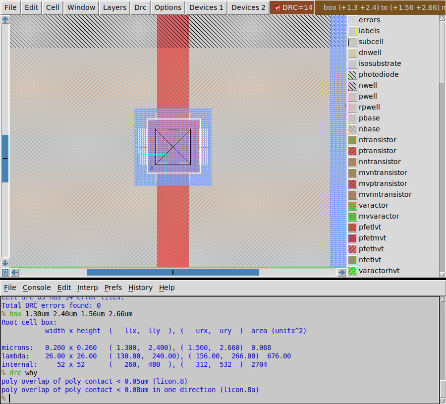
What that looks like Cell
drc_03, withDRC=14in the toolbar and white hatching around the poly contact.drc whynames the rule twice, once in its plain form and once in its “in one direction” form.Look up
licon.8in the DRC error decoder and work out what it protects.
You should see DRC=14 in the toolbar after drc check, and drc why naming licon.8 and licon.8a.
Part 3: Fix the first four cells
What does each rule protect, and what change satisfies it? For each of C=1 to C=4:
- Run
make why C=<n>to get the rule names. - Run
make edit C=<n>, thendrc checkin the console. - Put the box over a hatched area and run
drc why. - Look the rule up in the DRC error decoder, work out what it protects, and change the geometry to satisfy it with a comfortable margin. Work from what the rule asks for, rather than nudging shapes until the hatching disappears.
- Type
savein the console, then runmakein the terminal again.
The rules that two of the five cells break use the phrase “in one direction”. As Reading DRC errors explains with examples, it means that you pick an axis, x or y, and on that axis the outer layer must extend past the inner one by at least the rule’s amount on both sides. Only one axis needs to be generous, which is why the fix often costs you nothing.
If you get stuck, open the hint for that cell only, and only after you have tried.
diff/tap.8 is an enclosure rule. An implant mask has to extend past what it is implanting, because two masks never align perfectly.
li.5 is an enclosure rule: a wire has to overhang the contact under it. Paint the wire first, bigger than the contact, and then put the contact inside it.
licon.8 and licon.8a are enclosure rules. A 0.15 µm poly stripe is too narrow to hold a 0.17 µm contact, which is why gates get a landing pad.
li.3 is a spacing rule, so this violation means that two wires on different nets are too close together.
solutions/README.md in the package explains how to get unstuck without reading the answer.
You should see drc_01 to drc_04 at 0 in both DRC columns, still match in LVS.
Part 4: Fix drc_05
The default checker has reported drc_05 clean since your first run, yet the cell is wrong. Which tools notice, and what are they telling you? Look at how each one reports the problem before you fix it.
Two independent tools notice the problem. The first is the full rule set, which names these two rules:
All nwells must contain metal-connected N+ taps (nwell.4)
P-diff distance to N-tap must be < 15.0um (LU.3)
Both are context rules, which a cell can satisfy only with help from what is placed around it (Anatomy of a standard cell explains why).
The second is netgen, which reports a mismatch without ever using the word “tap”. Open
results/drc_05.lvs.spiceand find the PMOS line:X1 Y A VPWR w_0_600# sky130_fd_pr__pfet_01v8_hvt w=1 l=0.15What is
w_0_600#, and why is the PMOS body on it?TipAnswerw_0_600#is the PMOS body. It’s an invented node name, and the body is on it instead of on VPWR because the n-well tap has no contact on it, so nothing ties the well to VPWR.Fix it with the same loop as Part 3 (
make why C=5,make edit C=5,drc check,drc why), thensaveand runmake. This time, typedrc style drc(full)in Magic beforedrc check. Under the default rule set this cell has no violations, sodrc whywould have nothing to name.If you had only run the default rule set, what would have told you about this cell?
TipAnswerNetgen would have. LVS reported
Netlists do not matchon a cell that the default rule set called clean.
The habit to take from this part is the rule of thumb from The full DRC rule set: before you believe a DRC count of zero, run drc style drc(full). The labs that run DRC show you both counts, but tools outside this course won’t do that for you.
You should see drc_05 at 0 under both rule sets and match in LVS, and make ending in PASS.
Part 5: Erase instead of fix
What happens if you make a violation go away by deleting the shape that broke the rule? You could take every one of these cells to zero violations that way, so try it once, on drc_04.
Run
make edit C=4, erase theApad, andsave. Before you runmake, predict what it will show in the DRC and LVS columns fordrc_04.Run
make. The li spacing error is gone, andmakesays:Note: drc_04 is clean and no longer an inverter. Erasing the shape that broke the rule is not a fix. Move it, resize it, or add the thing it needed - the circuit has to survive.Why does this lab run LVS on all five cells, and not only on
drc_05?TipAnswerBecause a change that satisfies DRC can break the circuit, as erasing the pad just did. A layout has two jobs, passing the rules and being the right circuit, and a change that does one at the expense of the other hasn’t moved you forward.
Put the pad back the way you had fixed it (
uin the layout window undoes the erase, or repaint it),save, and runmakeagain.
You should see the note in step 2, and drc_04 back to match after step 3.
Finishing
You’re done when make ends in PASS, with all five of your fixed cells at 0 violations under both rule sets and match in LVS.
Questions:
- What does “in one direction” mean in a rule name? Part 3 explains it.
- Which cell would you have shipped broken if you had only run the default rule set, and what would have warned you? Part 4, step 4 answers it.
Submit: nothing for this lab.
Going further (optional)
To start again or check your answers:
make reset        # throw your fixes away and rebuild the five broken cells
make solutions    # write the answer key into solutions/
tcl/make_broken.tcl generates the broken cells and has one BREAK comment for each change, so it doubles as the answer key. Read it after you finish, not before.
Next on the Course path: read Stick diagrams, Extraction and Layout versus schematic (LVS), then do Lab 03: Draw an inverter.