The router in one page
This page answers: what do you need to know about the router to write a test for it, before you’ve read the whole specification?
The router’s specification is the page The packet router, and you write every router testbench in this course from it. It describes the router’s pins cycle by cycle, which makes it long. This page covers the same design with only the detail that your tests depend on, and each section links to the parts of the specification it comes from. When you need a cycle-by-cycle answer, follow the link. The specification’s timing examples, E1 to E9, are tables that labs/common/smoke/tb_examples.sv prints during a run of the RTL, so each one is a record of what the RTL did.
The blocks
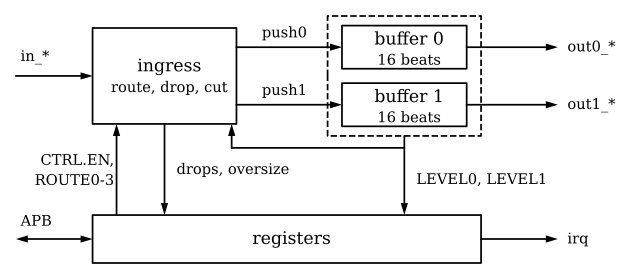
ready going the other way.The RTL is in labs/common/rtl/, 730 lines in five files. One file is a package of sizes and register offsets, three files hold the three kinds of block (the two buffers are two instances of router_fifo), and the fifth is the top module, router, which connects the blocks. You don’t need to read the RTL, and from Lab 02 on you’ll be testing faulty builds of it that you can’t trust anyway, but this is how the blocks divide the work:
- The ingress takes packets from the input stream. When a packet’s header arrives, the ingress looks up the routing table and the level of the output that the route names, and decides once, for the whole packet, whether to write it into that output’s buffer or to drop it. It also cuts a packet that is longer than 8 beats, and it reports every drop and every oversize packet to the registers.
- Each buffer holds up to 16 beats, 15 in a small RAM and one in the register that drives the output pins, so
out0_valid,out0_dataandout0_lastcome straight from flip-flops. A buffer’s level is the number of beats it holds, including the one on the pins. - The registers are the APB slave. They hold the configuration that the ingress uses (
CTRL.ENand the fourROUTEentries), record drops inSTATUSandDROP_CNTand oversize packets inSTATUSalone, read back both levels inLEVEL, and driveirqfromSTATUSandINT_EN.
The sizes are small on purpose, so that a short simulation can reach every corner of the design. Beats are 8 bits, there are 4 routes and 2 outputs, packets are 1 to 8 beats long, each buffer holds 16 beats, and the drop counters stop at 255 (Sizes).
Ports
Everything happens on the rising edge of clk, the APB port included, and the router samples its inputs there (Ports, Cycles and handshakes).
| Group | Inputs | Outputs | Notes |
|---|---|---|---|
| Clock and reset | clk, rst_n |
rst_n is active low and asynchronous |
|
| APB slave | psel, penable, pwrite, paddr[7:0], pwdata[31:0] |
prdata[31:0], pready, pslverr |
APB3 with one slave select and no PSTRB, so a write writes the whole register |
| Interrupt | irq |
active high, a level | |
| Input stream | in_valid, in_data[7:0], in_last |
in_ready |
the testbench is the source |
| Output 0 | out0_ready |
out0_valid, out0_data[7:0], out0_last |
the testbench is the sink |
| Output 1 | out1_ready |
out1_valid, out1_data[7:0], out1_last |
the same as output 0 |
A handshake happens in a cycle where valid and ready are both 1, and the beat moves at the rising edge that ends that cycle. The course’s Python testbenches change the router’s inputs just after a rising edge and sample its outputs at the falling edge, in the middle of the cycle, so no signal changes at the moment it’s sampled.
Verilator has only the values 0 and 1, so a data signal whose valid is low still holds some value, usually the last beat it carried. Never compare out0_data or out0_last in a cycle where out0_valid is 0, because what you’d be comparing is most likely left over from an earlier beat.
Packets and routing
A packet is 1 to 8 beats on the input stream. Its first beat is the header, and the beat with in_last = 1 ends it. The header’s bits 7:6 are DST, which picks one of the four routing table entries, ROUTE0 to ROUTE3. Bits 5:0 are a tag that the router passes through untouched, and the labs’ testbenches put the packet’s sequence number there. A delivered packet comes out exactly as it went in, except that an oversize packet is cut to 8 beats, as the end of this section describes (Packets).
The router decides what happens to a packet once, in the cycle its header is accepted. It uses ROUTE[DST] and the level of the output that the entry’s PORT names, both as they are in that cycle (Routing):
ROUTE[DST].EN |
Level of output PORT |
The packet is | Counted in |
|---|---|---|---|
| 0 | anything | dropped | NOROUTE_CNT, STATUS.NOROUTE |
| 1 | 9 to 16 | dropped | FULL_CNT, STATUS.FULL |
| 1 | 0 to 8 | written, beat by beat, into output PORT’s buffer |
The decision holds for the whole packet. If software writes ROUTE[DST] or CTRL while a packet is coming in, or either level changes, only later packets are affected. A header accepted in the cycle after the write completes uses the new value, and a header accepted in the same cycle that the write completes uses the old one. A dropped packet is still taken from the input, with in_ready at 1 for every beat, so a full output never holds up packets for the other one.
These three details of admission matter when you write a scoreboard:
- A packet is admitted only at a level of 8 or less, and it’s at most 8 beats long, so an admitted packet always fits in the 16-beat buffer. With output 0 stalled, two 8-beat packets are admitted, at levels 0 and 8, and a third is dropped. Nine 1-beat packets are admitted, at levels 0 to 8, and a tenth is dropped.
- The level in the header’s cycle counts every beat written into the output in earlier cycles, minus every beat taken by an output handshake in earlier cycles. Neither the header itself nor a handshake on the output in the same cycle counts. The beats written into an output are the input beats of the packets that your testbench predicts go there, and the beats taken are the handshakes on that output’s pins, so a testbench can track both levels exactly and predict every FULL drop.
- A packet for a disabled route is a NOROUTE drop whatever the level of the output its
PORTnames, and it’s never counted as FULL as well.
At the edge that ends the header’s cycle, a drop adds one to its counter, unless the counter is already 255, and sets its STATUS bit (Dropped packets).
A packet is oversize if its 8th beat doesn’t have in_last = 1. In the cycle the router accepts that beat, it sets STATUS.OVERSIZE, which reads 1 from the next cycle. If the packet is being forwarded, the 8th beat goes out with out_last = 1. The router then takes the rest of the packet from the input and throws it away, up to and including the beat with in_last = 1. An oversize packet that is also dropped is counted once, as a drop, and sets STATUS.OVERSIZE as well. DROP_CNT has no counter for oversize packets (Oversize packets).
Timing
| What | When | In the specification |
|---|---|---|
in_ready between packets |
equals CTRL.EN, which resets to 0 |
Enabling the router |
in_ready inside a packet |
1 from its first handshake to its last, whatever CTRL.EN, the routes and the outputs do |
rule I6 |
| A beat into an empty output | on the pins 2 cycles after its input handshake (E2) | The outputs |
| Beat \(k\) of an output | on the pins from cycle \(\max(t_k + 2,\; h_{k-1} + 1)\) until the cycle \(h_k\) in which it’s taken, where \(t_k\) is the cycle of its input handshake | rule O8 |
| A stalled output | holds its beat, unchanged, until the sink takes it, while the other output and the input carry on | rules O1, O2, O7 |
| An APB write | 2 cycles (setup, one access cycle); the register changes at the edge that ends the access cycle | APB |
| An APB read | 3 cycles (setup, two access cycles); it returns the value the register had in the first access cycle | rule A8 |
| A drop, or an oversize packet | for a drop, its STATUS bit and its counter change from the cycle after the header; for an oversize packet, STATUS.OVERSIZE changes from the cycle after the 8th beat |
E4, E5, E6 |
irq |
changes in the same cycle as the STATUS or INT_EN bit that changes it |
INT_EN |
Register map
Addresses are byte addresses, every register is 32 bits, and bits not listed read 0 and ignore writes (Register map).
| Address | Register | Access | Reset | Fields | UVM access |
|---|---|---|---|---|---|
0x00 |
ID |
read-only | 0xD105_0001 |
[31:0] design 105, revision 1 | RO |
0x04 |
CTRL |
read-write | 0 | [0] EN |
RW |
0x08 |
STATUS |
write 1 to clear | 0 | [0] NOROUTE, [1] FULL, [2] OVERSIZE |
W1C, volatile |
0x0C |
INT_EN |
read-write | 0 | [0] NOROUTE, [1] FULL, [2] OVERSIZE |
RW |
0x10 |
DROP_CNT |
read-only; any write clears both | 0 | [7:0] NOROUTE_CNT, [15:8] FULL_CNT |
WC, volatile |
0x14 |
LEVEL |
read-only | 0 | [4:0] LEVEL0, [12:8] LEVEL1 |
RO, volatile |
0x20, 0x24, 0x28, 0x2C |
ROUTE0 to ROUTE3 |
read-write | 0 | [0] EN, [1] PORT |
RW |
The other 246 of the 256 addresses are bad. They are 0x18, 0x1C, everything from 0x30 to 0xFF, and every address that isn’t a multiple of 4. A transfer to a bad address takes the same number of cycles as any other and completes with pslverr = 1. A bad write changes nothing, and a bad read returns 0. Writing ID, LEVEL or the reserved bits of any register isn’t an error: the transfer completes with pslverr = 0 and the write is ignored.
Four details of the registers catch people out:
- \(\texttt{irq} = \bigvee_{i} (\texttt{STATUS}[i] \wedge \texttt{INT\_EN}[i])\), with no delay.
INT_ENdoesn’t stopSTATUSrecording events; it only decides which ones raiseirq. - If an event sets a
STATUSbit in the same cycle that a write clears it, the event wins and the bit stays 1 (STATUS). - A write to
DROP_CNTin the cycle of a drop clears the counter first and then counts the drop, so the counter reads 1 afterwards (E9, DROP_CNT). PORTkeeps its value whileENis 0, but has no effect then (ROUTE0 to ROUTE3).
Reset
rst_n is asynchronous. When it falls, the whole router resets at once, without waiting for a clock edge, and the router runs normally again from the first rising edge after rst_n returns to 1. While it’s low, in_ready, both out_valids, irq, pslverr and prdata are 0 and pready is 1 (with the bus idle). Every register goes back to its reset value, so every route is disabled and CTRL.EN is 0, and nothing gets through until software sets them up again. Both buffers are emptied and any packet in flight is lost, so nothing from before the reset comes out afterwards, not even a beat that was waiting on a stalled output (E8). The router’s state is undefined until its first reset, so hold rst_n low through at least one rising edge at the start of every simulation (Reset).
The rules
The table below gives each numbered rule from the specification’s Valid/ready rules and APB rules sections in one line. The rules marked testbench are for your stimulus to keep, and the router assumes them without checking them. The specification also says how to check each kind of rule. Most rules are properties over one or two cycles, and each of those becomes a plain assertion. O5, O6 and O8 need state kept for each output, so they belong in a scoreboard, or in assertions with tracking code beside them. I4, O3 and O7 say what a signal does not depend on, which no single trace can show; a reference model checks them, and so does a test that changes an input in the middle of a cycle.
The rules about normal operation hold only while rst_n is 1. I7, the first halves of O4 and A4, and the reset values say what holds while it’s 0.
| Rule | Whose | What it says |
|---|---|---|
| I1 | testbench | Once in_valid is 1, it stays 1 until the handshake or a reset. |
| I2 | testbench | While in_valid is 1 and in_ready is 0, in_data and in_last don’t change. |
| I3 | testbench | After a reset, the first beat the source offers is the header of a new packet. |
| I4 | router | in_ready doesn’t depend on in_valid, in_data or in_last in the same cycle. |
| I5 | router | Between packets, in_ready equals CTRL.EN. |
| I6 | router | From a packet’s first handshake to its last, in_ready is 1, unless rst_n falls. |
| I7 | router | in_ready is 0 while rst_n is 0. |
| O1 | router | Once out_valid is 1, it stays 1 until the handshake or a reset. |
| O2 | router | While out_valid is 1 and out_ready is 0, out_data and out_last don’t change. |
| O3 | router | out_valid, out_data and out_last don’t depend on any input in the same cycle. |
| O4 | router | out_valid is 0 during reset, and after it until a beat accepted after the reset reaches the output. |
| O5 | router | An output delivers its packets’ beats in the order the router accepted them, unchanged except for a cut packet’s out_last, and never interleaved. |
| O6 | router | Every output packet is 1 to 8 beats and ends with the only beat that has out_last = 1, unless a reset cuts it short. |
| O7 | router | Nothing about output 0 depends on out1_ready, and nothing about output 1 depends on out0_ready. |
| O8 | router | Beat \(k\) is on the output from cycle \(\max(t_k + 2, h_{k-1} + 1)\) until it’s taken, and out_valid is 0 otherwise. |
| A1 | testbench | A transfer is one setup cycle followed at once by its access cycles. |
| A2 | testbench | paddr, pwrite and a write’s pwdata hold from the setup cycle to the end of the transfer. |
| A3 | testbench | In the cycle after a transfer completes, penable is 0. |
| A4 | testbench | psel is 0 during reset; a transfer cut by a reset has no effect. |
| A5 | router | In a write’s first access cycle, pready is 1. |
| A6 | router | In a read’s first access cycle pready is 0, and in its second it’s 1; it’s 0 at no other time. |
| A7 | router | pslverr is 1 only in the cycle a transfer to a bad address completes. |
| A8 | router | A completing read’s prdata is the register’s value in the first access cycle (0 for a bad address), and prdata changes only at the end of a read’s first access cycle and when rst_n falls. |
| A9 | router | A good write takes effect at the end of its access cycle, by the register’s access type. |
Check yourself
ROUTE0is0x1,CTRL.ENis 1, and output 0 is stalled with seven 1-beat packets in its buffer. An 8-beat packet forDST0 arrives, then a 1-beat one. What happens to each?TipAnswerThe 8-beat packet’s header sees a level of 7, which is 8 or less, so the packet is admitted, and its 8 beats take the level to 15. The 1-beat packet’s header then sees 15, so it’s dropped as FULL:
FULL_CNTgoes up by one andSTATUS.FULLis set from the next cycle.All four routes are disabled and output 1 is full. A packet for
DST3, whoseROUTE3.PORTis 1, comes in. Which counter goes up?TipAnswerNOROUTE_CNT, and only that one. A packet for a disabled route is a NOROUTE drop whatever the level of the output itsPORTnames.ROUTE1is 0. Your test writes0x3to it, and the write completes in the same cycle that a header withDST1 is accepted. Where does the packet go?TipAnswerNowhere. It’s dropped as NOROUTE, because a header accepted in the cycle that a write completes uses the register’s old value, and the new value applies only from the next cycle.